Winter 2024 Course Review: EECS 311
2024-05-03
Course Title: Analog Circuits
Rating: 3/5
Instructor (David Garmire)
On the first lecture I had a feeling I've seen him before. I checked the "courses offered" spreadsheet at SJTU last semester, and he taught 281.
He's all nice and stuff, and he never judges you. But the vibes are not the best I could imagine. He's pretty reserved, and often seems in doubt of himself, as if he's teaching it for the first time. Contrary to two other EECS professors I had this semester, he had the least "authority figure" vibes. (Robert Dick sometimes has too much; Brian Noble has it just right.) Sometimes we can't tell if we're wrong or he's wrong. If we point out he might be wrong, he stops right away, which is good, but his first assumption is always he is wrong, which hurts credibility if he's not.
One thing I like about David Garmire is his analogies. The best one is how the NPN BJT is like a leaky tub of water.
Course topics
- Introduction & review (e.g. Laplace transform, Bode plots)
- Opamps
- Inverting & non-inverting amplifiers
- Nonidealities
- Sallen & Key filters
- Diodes
- BJTs
- CE, CC and CB configurations
- High frequency
- Degeneration
- MOSFETs
- CS, CG and CD configurations
- High frequency
- Degeneration
Personal reflections
Compared to EE majors in the room, I was all chill about this course. I enrolled because I was interested, not because I was required to. It's not like my degree or life depended on it. But my life does depend on music, and it's part analog circuitry.
Personally, I think Sallen & Key (S&K) just came out of nowhere. There was no motivation. It's just a table of equations that we use to solve for like six unknowns. It's not fun.
BJTs are the most complex topic. You've got three currents coming in or out of the BJT, one of which can sometimes be ignored. You have three modes: cutoff, active and saturation. To make a useful amplifier, you have to juggle the voltage correctly to bias it in the right range; then you get a transconductance, then you convert it to a linear circuit with a dependent current source, then you either do a bunch of nodal analysis or just apply formulas. In most cases formulas Just Work™.
I remember taking 215 (the OG circuits course) and scoffing at the notion of a "voltage-dependent current source". Like who would use that in real life? I bet you ten bucks you can't even build one. However, it turns out if you apply superposition principle to a non-linear circuit, and constrain your input to a narrow range to pretend it was linear, an "X-dependent Y source" appears, and it helps you apply linear formulas to an otherwise unholy "e to the power of v over something" pasta.
MOSFETs are just BJTs but with different names for everything (the "active region" of the BJT is analogous to "saturation mode" of MOSFETs). Also one of the three currents is gone (except in high frequency) and you juggle the voltages in a different way.
Overall, this course was more inspiring and extensive than I thought. However, it was also pretty elementary. I enrolled because two of my hobbies (ham radio and music) are closely relevant to analog circuits, and I had hoped to build an amp after this course. Although half of the course is building amps, it's pretty theoretical.
Building amps
The majority of our discussion toward the second half of the course was transistor-based amplifiers. Interest was mostly on NPN common-emitter or NFET common-source, but there are other configurations to fit niches. We had these parameters to optimize for:
- Gain (open-circuit, loaded, or overall)
- Output voltage swing (how many Vpp can you output before clipping)
- Bandwidth (low & high 3dB cutoff)
- Output impedance (affects loaded gain)
- Input impedance (affects overall gain)
- Power dissipation (how much DC power does it draw)
Desiging amps, especially multi-stage ones such as what I did in lab 5, is an ardous chain of trial and error. My observations are
- Build first stage with around 10x the signal impedance
- Think about gain first
- 1 mA is usually a good DC current to start with
- If it doesn't work, try 1.5 or 2
- DC current determines gain, output impedance, and power
- Too little and too much current both lead to bad overall gain
- Decouple all stages by chucking in a 1 µF to 47 µF cap
- If load impedance is small, add a buffer at the last stage
- Bandwidth is the last thing to worry about
- If you need to squash highs, add a cap from a signal to ground
- If you need more lows to pass, use larger decoupling caps
Those tradeoffs are an inevitable part of an electronic engineer's life. Besides, some transistor parameters (such as beta) depend on temperature and fab variations, so we had to add feedback to make our circuit less susceptable. I now appreciate the amount of work that analog engineers go through just to create a usable amp.
Sine wave breakdown & shoutout to Samuel
Another way to look at amp-building in the scope of 311 is to break down a sine wave:
x(t) = A * sin(ωt + ɸ) + b
- A: amplitude, or in our case, gain. We talk a lot about gain. Arguably the point of amps is gain.
- ω: frequency. We spent two lectures on high frequency response, one for BJTs and one for MOSFETs, which discuss internal capacitances within the transistors. The effect of external capacitors is discussed in the first half of the course, in analog filters.
- ɸ: phase. We hardly ever talked about phase, and phase Bode plots were not required. However we were required to tell apart inverting and non-inverting amps.
- b: DC offset. In general not a thing to worry too much about. If you need to get rid of it, just add a cap. If you need it back, bias your base/gate/whatever. It's just a stepping stone for the AC signal.
The frequency discussion is very interesting. We used a duo of methods called OCTC and SCTC (open/short circuit time constant) to estimate the lower and upper 3dB cutoff frequencies. They work like magic. Two separate occasions, the estimate I got with them is within 1% of SPICE simulations. Huge kudos to Samuel Nolan, our IA, for explaining the methods in the lab. He is the GOAT IA this semester.
Analog vs. digital
On the first 311 lecture, David Garmire talked about the quote unquote "superiority" of analog circuits over digital ones, such as energy efficiency. Somewhat ironically, exams two and three had one design problem on each, and the premises are both to design an amplifier for an ADC, presumably into a chain of DSP algorithms.
Many systems now use DSP, which often is cheaper and/or more noise-proof, so unless you're an retro-audiophile or still live in the 1900's, very few things actually have analog circuitry from top to bottom. They usually have at least one piece of integrated circuit somewhere. But even if it is the case — he argues — analog circuits are essential.
There was a 373 lecture dedicated to ADC/DAC, and later there were a few slides that discuss analog filters. It was one of the few occasions this semester that 311 was useful for another course. I am more than sure it'll be useful for 473 next semester as well.
Robert Dick acknowledges that sometimes there are problems 1's and 0's cannot solve. One such example is high frequency noises in the ADC input, which cause aliasing, and are a pain to distinguish from actual signal in software. So the solution is to add a lowpass filter to the input.
I am unsure whether my preference is analog or digital. On one hand, analog is cool because my bass is an analog system. But the DAW is digital (it literally stands for digital audio workstation). Let's leave it this way.
Labs
Labs are the heaviest workload of 311. There are five labs in total, each spanning over two or three weeks.
- Lab 1A/B: opamps
- Lab 2A/B: S&K filters with opamps
- Lab 3A/B: voltage boosting & power harvesting with diodes
- Lab 4A/B: single-stage BJT amp, measuring beta and capacitances of BJT
- Lab 5: designing a 3-stage amp
The typical roadmap of a lab:
- Prelab: Do calculations, simulate in SPICE
- In-lab: Build circuit, measure with ADALM and Scopy
Note:
- The ADALM is a virtual lab kit USB device by Analog Devices
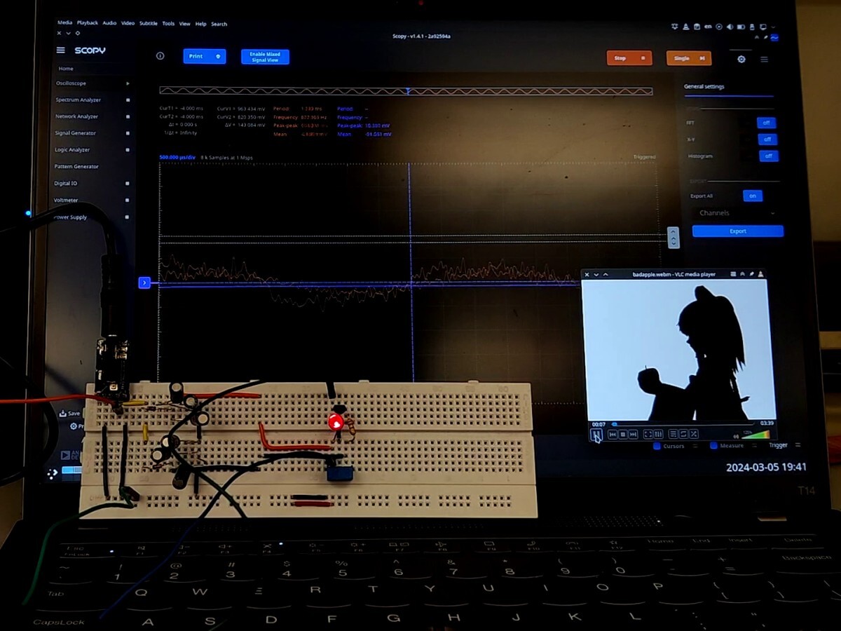
- Scopy is the software to interface with the ADALM. It's got an oscilloscope, a voltage supply, a multimeter, and a network analyzer (which you use to get Bode plots). Thankfully it is open source and runs on Linux (was a pain to install though because it's not in any pacman repo or AUR. Had to manually build it because I didn't want flatpak. Somehow it wanted a patched version of Qt and many other deps so I had to build like six libraries and manually change CMakeLists so one of them compiles)
- SPICE is a circuit simulator. The lab docs mention LTSpice, which does not run on Linux, so I used ngspice integrated in KiCad. Halfway through the semester, KiCad upgraded to 8.0 which includes a major overhaul of the ngspice frontend — huge improvement.
In lab 3B, I built a circuit that harvests power from a 3.5mm jack to light up an LED. Naturally, I made it play Bad Apple:
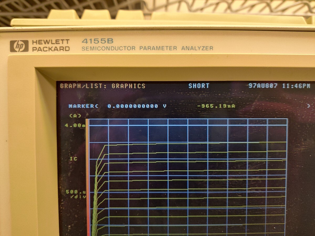
In lab 4B, I hooked an NPN BJT to a giant beast of a machine, the HP 4155B semiconductor parameter analyzer that thought it was 1997.
Despite not having an A/B, lab 5 took three weeks. After designing and simulating (but not building) a circuit, I needed to write a report for the design of my three-stage amp. It "must be written with a word processor", but did not mention which one.
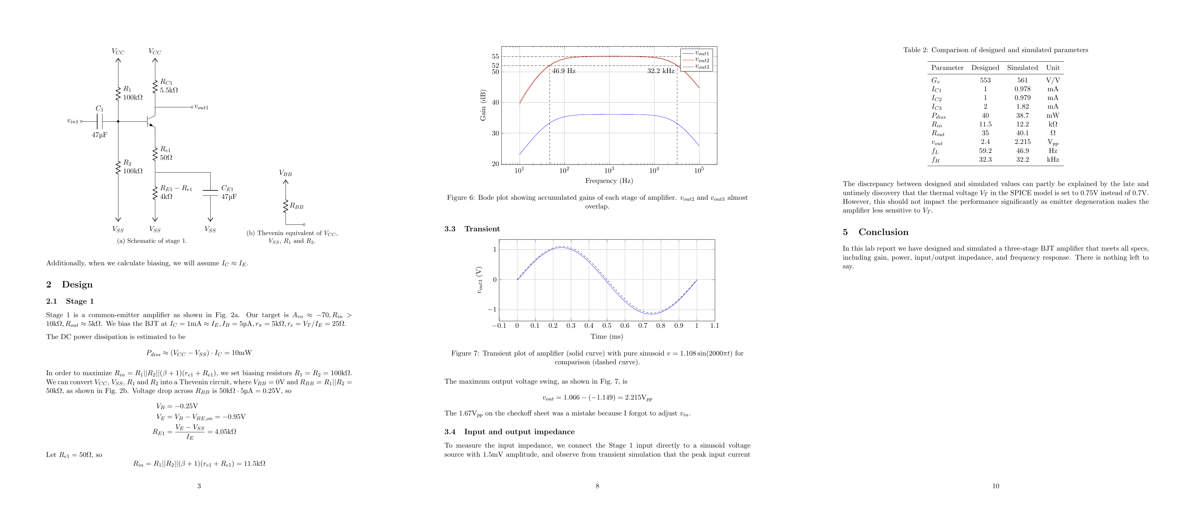
I used up like 10 pages of scratch paper (single sided) just for the calculations. Glad I did meet the specs.
Verdict
It's just a gateway drug to EE. Don't expect too much — you won't be an expert when you walk out, but do expect mind-bending moments, like how I discovered that I've been misunderstanding BJTs for like five years.
If your job involves interfacing with "weird" analog signals, like signal impedances in the megaohms, then this course is essential.
Would be better if the lab was larger though. It's like a can of sardines.