Wristbanditø: Reverse engineering the twenty one pilots wristband
First draft written 2025-09-22, finished and published 2026-07-11 because I famously never procrastinate
Wristband
The date is 2025-09-19. I am back from Cincinnati after the first show of twenty one pilots’ Clancy Tour: Breach. Apart from the live debut of 5 songs on the new record and Josh’s vocals (aka Jocals), they also gave each attendee an LED wristband made by a company called CrowdSync. And it looks very impressive when the entire stadium lights up.

▲ This was during "The Contract"
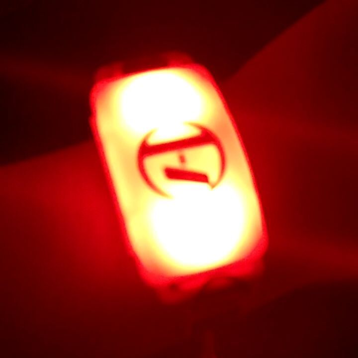
At the end of the show, it just stayed on, and to no one's surprise, the batteries died the next day. I tried putting in some new cells, but it won't do anything.
In an effort to stop it from being e-waste, I did the most natural thing an engineering student would do: I reverse engineered it.

Before actually taking it apart, I took an educated guess. It’s gotta be RF using an on-PCB antenna, and the IC is probably a black blob. The LEDs could be WS2812B (the ones they use in fancy RGB strips). With this expectation, I unscrewed it and pried it open.
Splitting It In Two, Two, Two, Two
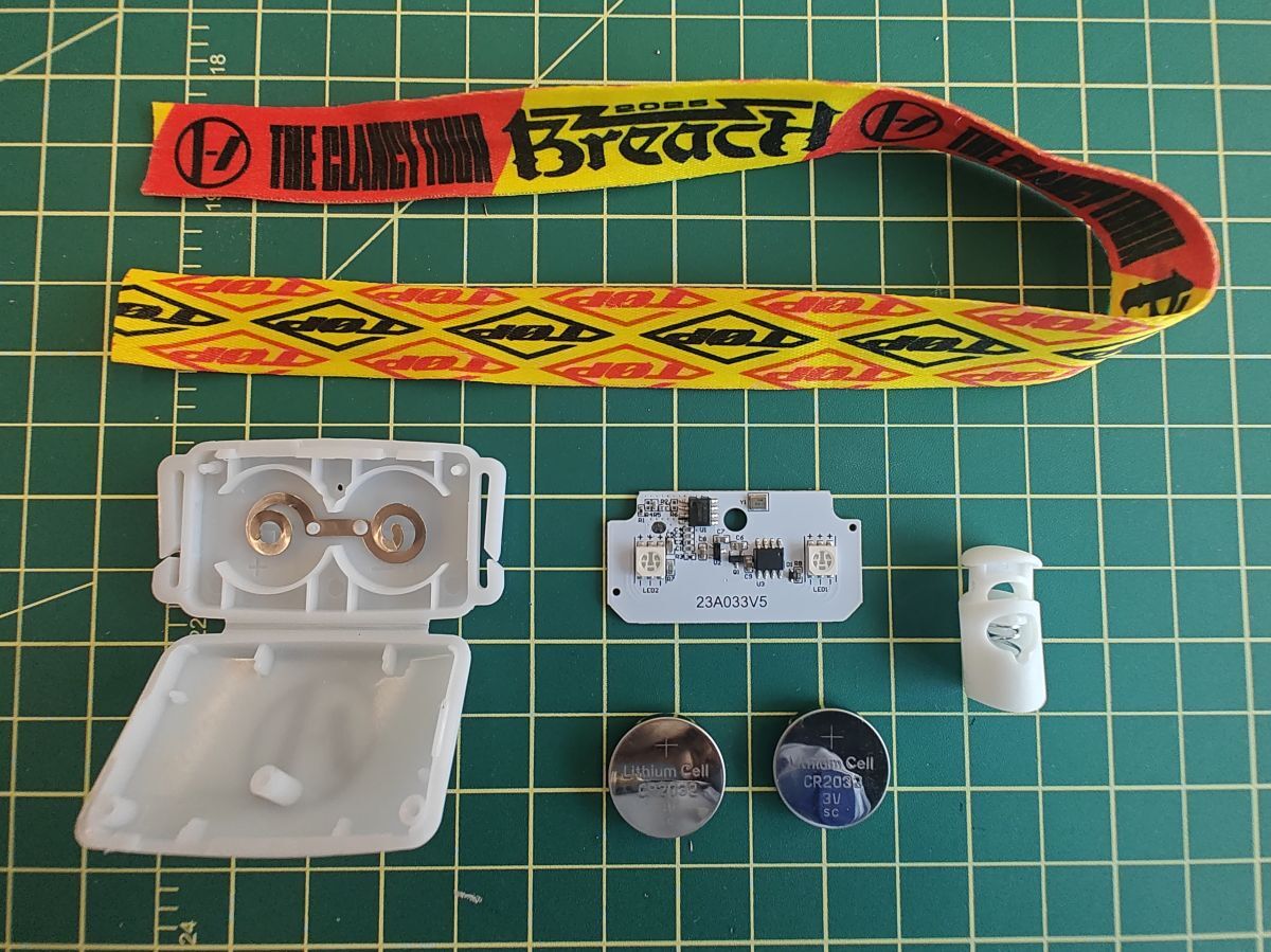
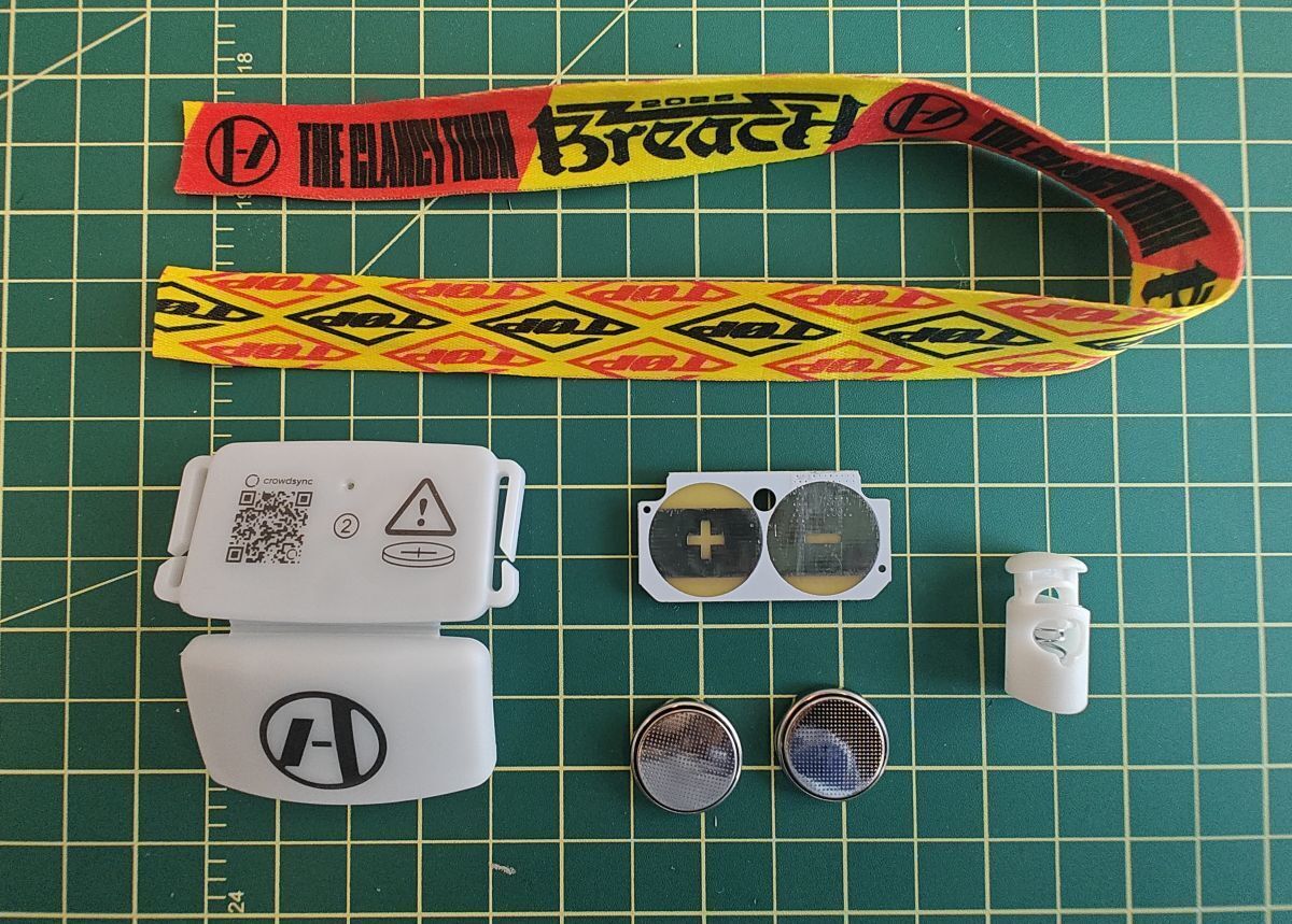
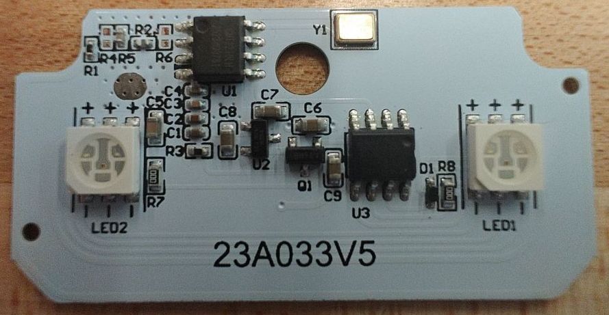
Inside the plastic case is a white PCB and two CR2032 coin cells in series. The PCB measures 45×23×0.8 mm. On the back is just the two terminals for the coin cells. On the front, I found some parts, looked up their markings for datasheets, and had a vague idea what they do. I’m quite surprised they were actual packaged ICs rather than black blobs.
- U1: marked "CMT2210LH 2523DQ0781", ISM-band OOK receiver, SOIC-8
- U2: marked "662K UMW 521", 3.3V LDO, SOT-23-3
- U3: unmarked, gotta be an MCU, SOIC-8
- Q1: marked "A1SHB" with an overline on S, PMOS, SOT-23-3
- LED1,2: common anode RGB, 5×5 mm
- Y1: 27.1412 MHz quartz crystal
The radio receiver IC is the CMT2210LH, whic receives at 433.92 MHz. The antenna is just a copper trace going around the edge of the PCB. It is unrealistic to expect a cheap device to have any dedicated antenna.
The RGB LEDs are actually wired in parallel in that the red cathodes of both LEDs are connected, so are green, so are blue, and all six diodes share a common anode. This means both LEDs show the same color at any given time. This is reasonable because the MCU only has 8 pins. Now the question is, what is the MCU?

With a glimpse of visual aid and poking around with a multimeter in continuity mode, I drew the following schematic:
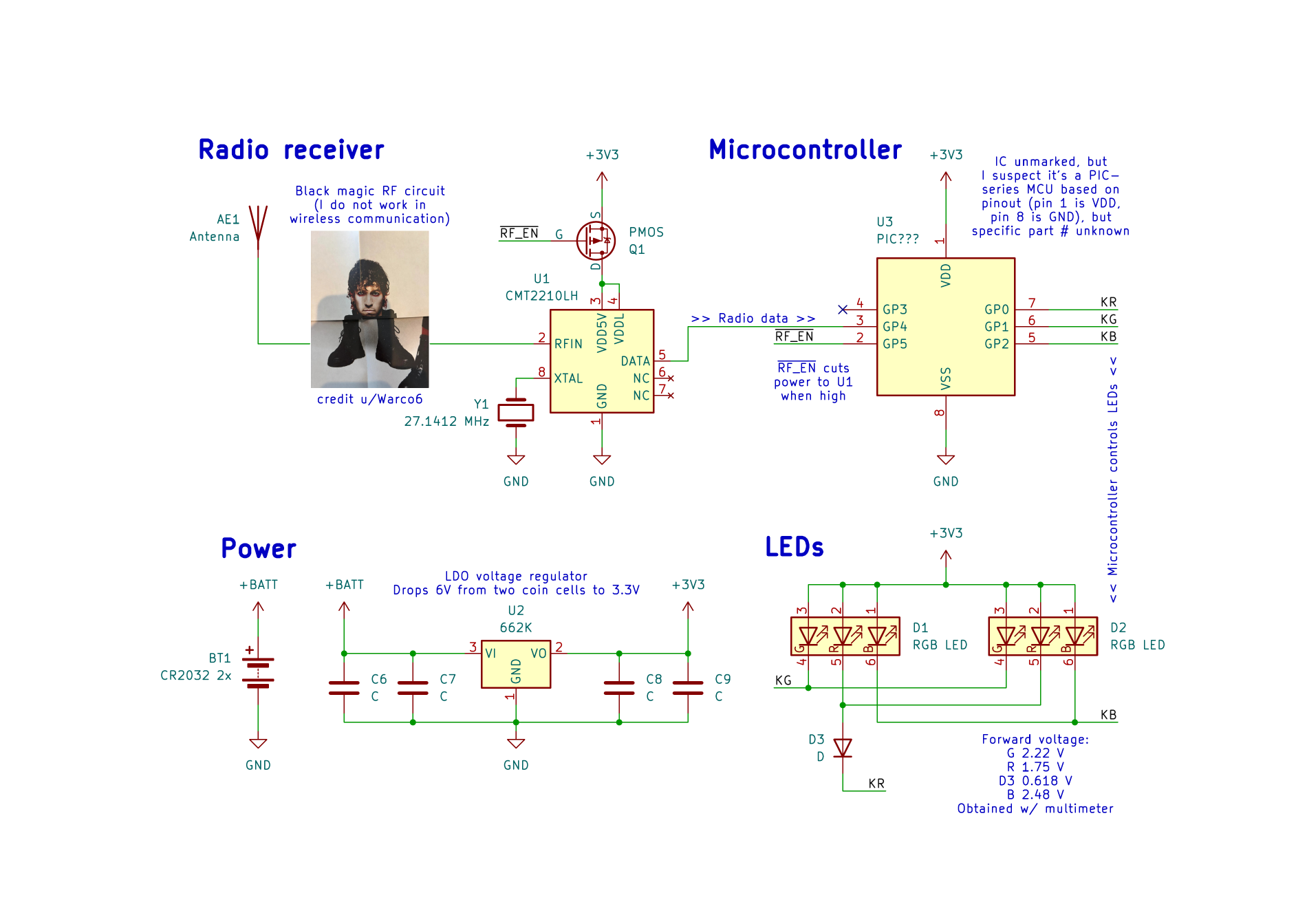
The MCU has its ground pin at pin 8 and VDD at 1, which is a huge clue. I looked around for SOIC-8 MCUs, and concluded that they’re neither AVRs nor 8051s. The PIC series, however, has a pinout that looks right. It’s likely that the company is buying cheap clones, given they’re unmarked.
I was puzzled by the lack of current-limiting resistors on the LEDs (the red had a diode to take away some voltage drop). Maybe the MCU itself has a limit?
Also, I haven’t figured out what the 0-ohm resistors (R7 and R8) are for.
But how do I turn it on
Though I now know how the LEDs are controlled, the radio transmission format remains unknown. A quick web search for “CrowdSync reverse engineer” only seems to yield results for PixMob. They may or may not be using the same format; I suspect not. Will I buy a Flipper Zero and another ticket just to find out? No.
At this point, these were the possible plans:
- Ideal plan: Reverse engineer RF packet format so I can control it wirelessly
- Method 1: Someone brings a Flipper Zero to a show and records all transmissions. However, it is not clear whether they will bring back the wristband on later shows.
- Method 2: Dump firmware from MCU and disassemble, decompile if possible, then figure out what the MCU expects.
- Plan B: Reprogram PIC MCU to display a preprogrammed pattern, bypassing all wireless communication.
Undocumented backdoor
I posted a Google Doc containing most of the above to the tøp subreddit. The next day, u/just_matty_dee commented that someone found a hack where if you short pins 3 and 4 on the MCU, it would cycle through the light patterns. And it worked!
Pin 3 is radio data input, and pin 4 is not connected. Is it possible that pin 4 was mocking radio data? I did not put it on an oscilloscope, so I don't know.
Modding time
Anyway, I was able to solder a button on it:
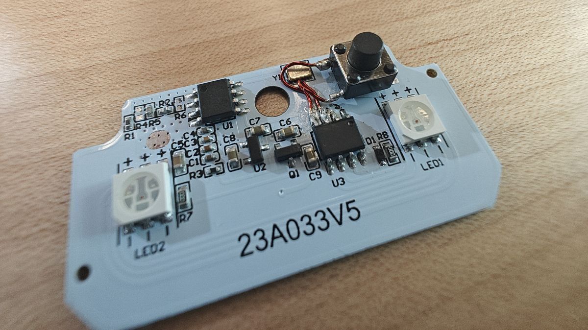
The button was too tall for the enclosure, so I decided to drill a hole in it:

Now, the button pokes through the hole and you can press it from the outside!
Conclusion
This is a simple reverse engineering project that is, in my opinion, done beautifully. However, it's not ideal that I had to do this in the first place. This wristband was designed to burn out within a few hours. Maybe you could reuse it at another show, or some other band's show, but chances are they'll hand out another wristband. They could have made it easier to switch it on and off, though it would involve more cost and compromise waterproofness (if there was any), and it's not remotely the most wasteful thing about the music industry.
Anyway, at least now I have a wristband I can show off.