Bikeblinkers
2022-01-13
I own a cheap bike.

Yes, this was what it literally looked like... when I rescued it from the bikeshed where a few more abandoned vehicles belong, in October 2021. Years of exposure to moisture and rain has rusted multiple mechanical joints.
Dad bought me the bike when I was around ten. I stopped riding it since high school because (a) Dad offered to drive me there and (b) it was in awful condition. Mom rode it to the gym on occasion, but always complained it felt shoddy.
Why rescue it then? Well, I was going to university, and the campus is not something you would want to navigate on foot. Not bothered to buy a new one, Dad and I scraped off the artifacts of oxidization and wiped it with oil (the bike, not the artifacts). We installed replacement tires, and tadaa, functional bike.
One month prior incidentally, in an unexpected chain of events — alright, the chain is only two events long — bike slipping sideways because I braked too hard, and me breaking my lunate bone.
🎖️ Achievement made: First Broken Bone
It was one of the smaller bones, but it still immobilized my left wrist. Also it wasn't my bike; it was one of those rental bikes which are quite ample on campus. Coupled with the fact that I got my driver's license in late August, I began to care about traffic safety even more.
The traffic law targeting bicycles says cyclists are required to indicate a turning. On an electric bike you probably already have the blinkers (shame on those who neglect them), but what if all you own is a human-powered crap of a bike? Sure, the convention is to just lift your left arm when turning left and vice versa, but the law also forbids either hand from letting go of the handlebar. I'm not nitpicking but clearly you could do better, Unknown Law Person(s).
There's gotta be a better way. And that is when I had the idea of making my own blinkers.
My first PCB
The days following my injury, I did some research. All I needed was two yellow light sources that blink at around 2 Hz, and ideally I would also be able to make them blink together to emulate a car's hazard light. The light source would obviously be LEDs, and the control would be a SP3T (single pole, three throw) switch and a self-maintaining push button. But how am I supposed to make them work?
What I needed to figure out were:
- How do I make something blink
- How to let one thing blink but not the other
- How to let them blink together if I want
It didn't take much trouble to find the solution to the first question — NE555. The 555, when connected to an external circuit that puts it to "astable mode", generates an alternating voltage on its output pin, the frequency of which can be fine-tuned with a few resistor and capacitor values. The circuit was simple enough to be drawn on paper, but I soon got tired of redrawing every so often. So I went with KiCad, which I had heard so many times but never tried..
🎖️ Achievement made: First EDA
Honestly it was quite fun, and following this tutorial by DigiKey on YouTube I had some basic understanding of how it works as a toolchain. Still incapable of producing anything of value, though (you'll see why in a moment.)
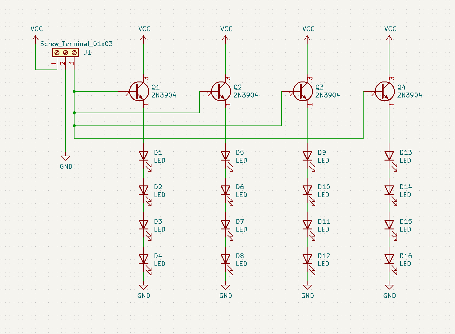
Before doing anything else I wanted to make sure KiCad is stable enough, so I laid out a simpler schematic for the LED panels:
🎖️ Achievement made: First schematic
Now, before you point out the mistake I made here (common collector configuration), I had little idea how BJTs work then (and still remain largely ignorant now). Regardless, they looked good to me, and it was time for me to turn it to a PCB.
I was intimidated by PCBs at first. I had no idea how the "copper wires" could connect all the components without intersecting, but most of my concern came from the multitude of vectors where things could go wrong, most of which out of my knowledge. Also, PCB fabrication wasn't as cheap as I would hope. My design could fail completely, ruining everything. Thankfully Kliment on IRC, who is miles ahead of me, encouraged me a lot. So guess what, I did it.
So basically to make a PCB you first transcribe symbols (components and stuff) from the schematic to footprints on the board. A footprint is generally some space on the PCB for you to solder something on or through pads, for example an LED, which has two pads, or the 555, which has eight. In this project I went for all THT (through-hole) parts because it is all I learned from soldering lessons up to high school. All footprints placed, you just run copper traces between the electrically connected pads, such as battery anode -> VCC pin of IC.
It took a lot of trial and error to route the tracks, given I "only" had two copper layers and had never learnt anything about vias, but the turnout, I thought, was pretty sweet:
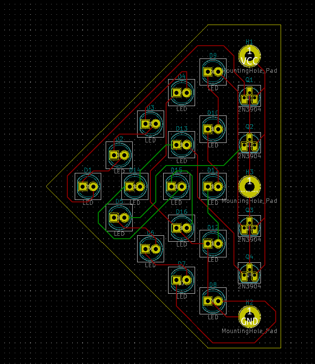
🎖️ Achievement made: First PCB design
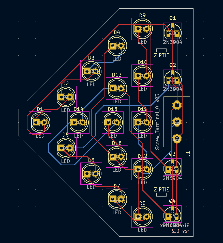
It took about a week (Sept 9-15) to improve my design with new connectors chosen (I honestly did not know what "Mounting Holes" are for) and based on suggestions from Kliment regarding that 90 degree turn above D4, and the outline of the board overall. The screenshot below is taken in KiCad 6.0, hence the different color scheme.
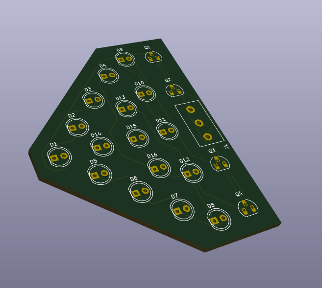
Man, I love 3D renderings.
555
At the same time I was also working on the controller circuit, the one with the 555 on it. Based on Wikipedia, I was able to work out the R and C values I needed, and experimented with a 555 on a breadboard.
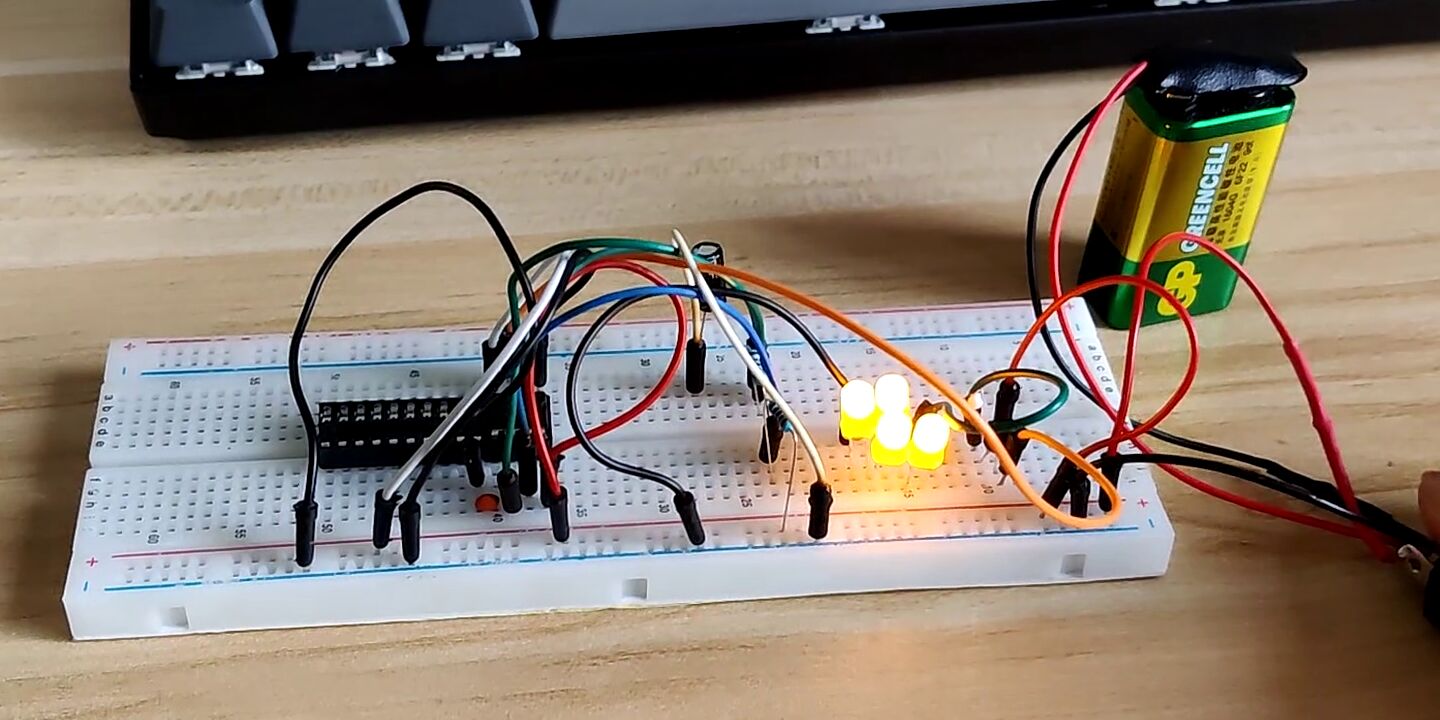
I was going to use a 9V battery, power the LEDs with it directly but have an LM7805 linear regulator convert that to 5V for the 555. However, Kliment pointed out it wasn't necessary and a 555 could operate under voltages as high as 18V; plus, an LM7805 is pretty power hungry.
The schematic looks like this:
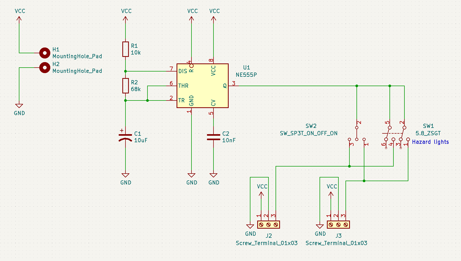
🎖️ Achievement made: First logic circuit without Arduino or any MCU
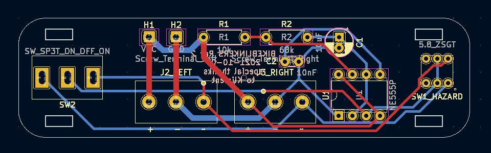
Okay, time to design another PCB.
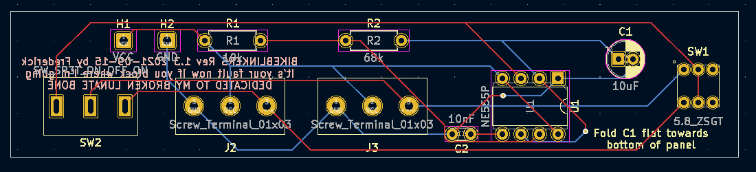
You might notice the tracks are not thick enough. They are 0.25mm thick, which is pretty wasteful of board space and unfavorable for current-carrying tracks. But as I had no experience, it went unnoticed.
The two PCB designs were finished at around the same time, so on October 1 I exported the Gerbers (a set of files factories rely on to etch, drill and cut out the PCBs) and sent a .zip of them to a manufacturer so they could turn my designs into physical objects.
And they came.
🎖️ Achievement made: First physical PCBs
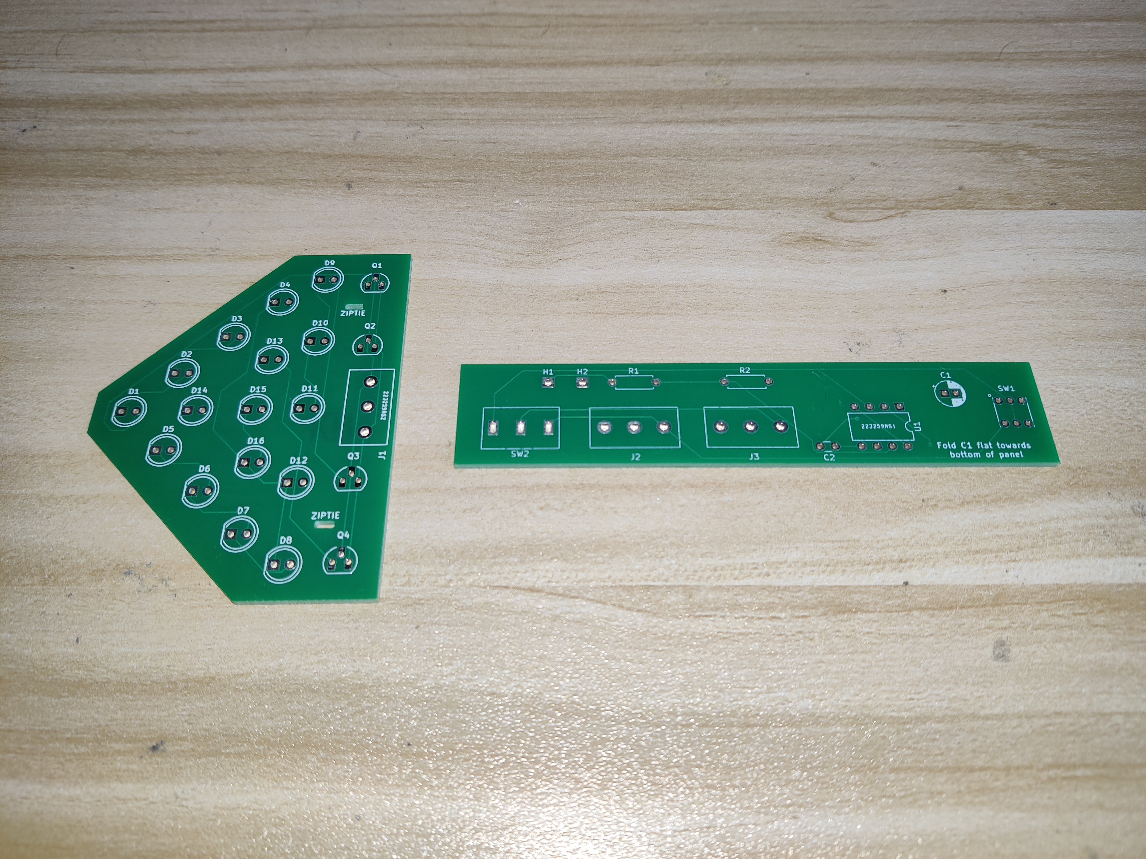
The moment I unsealed the vacuum package, my first impressions were:
- Wow, so green
- Smooth boi
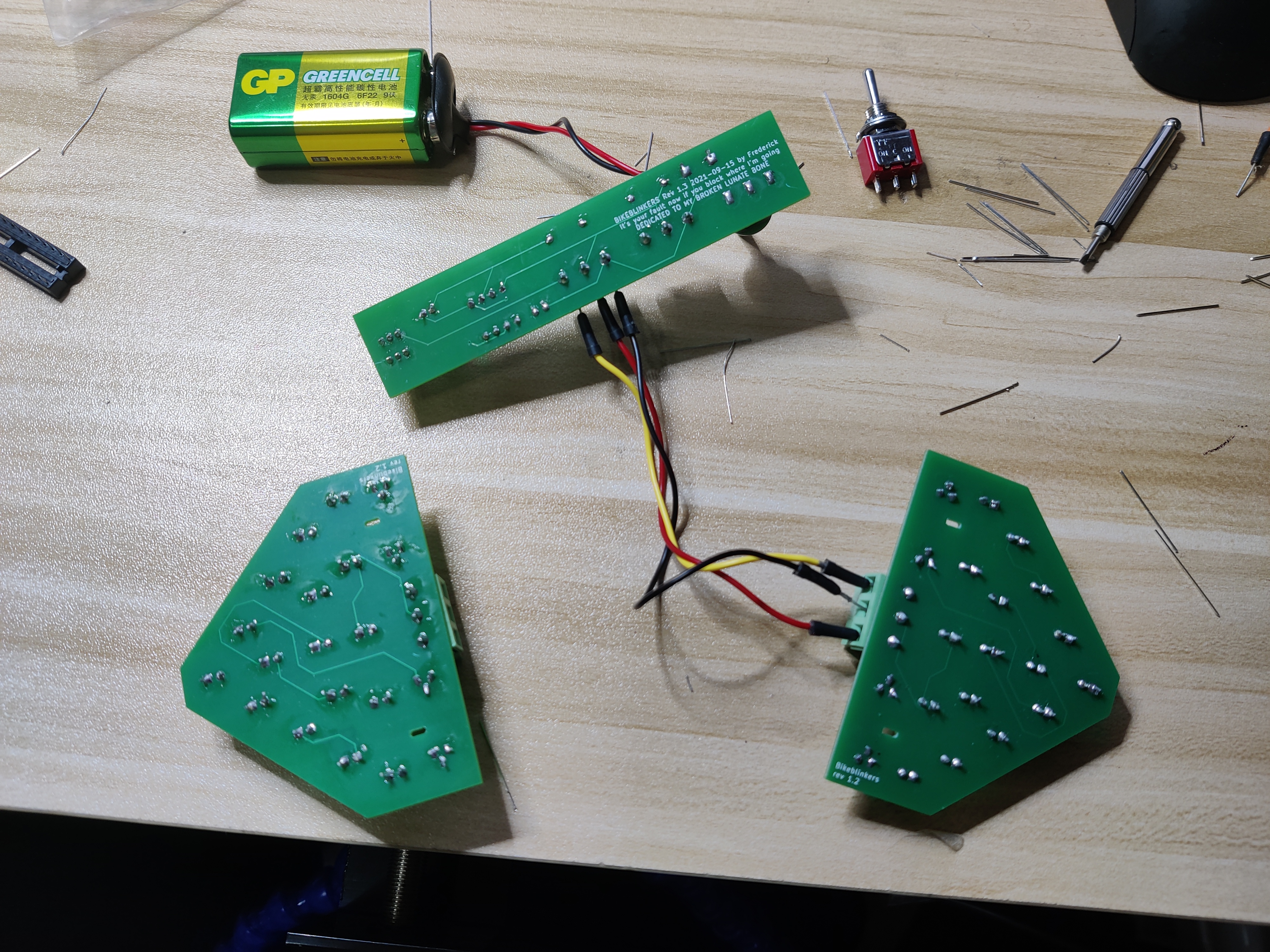
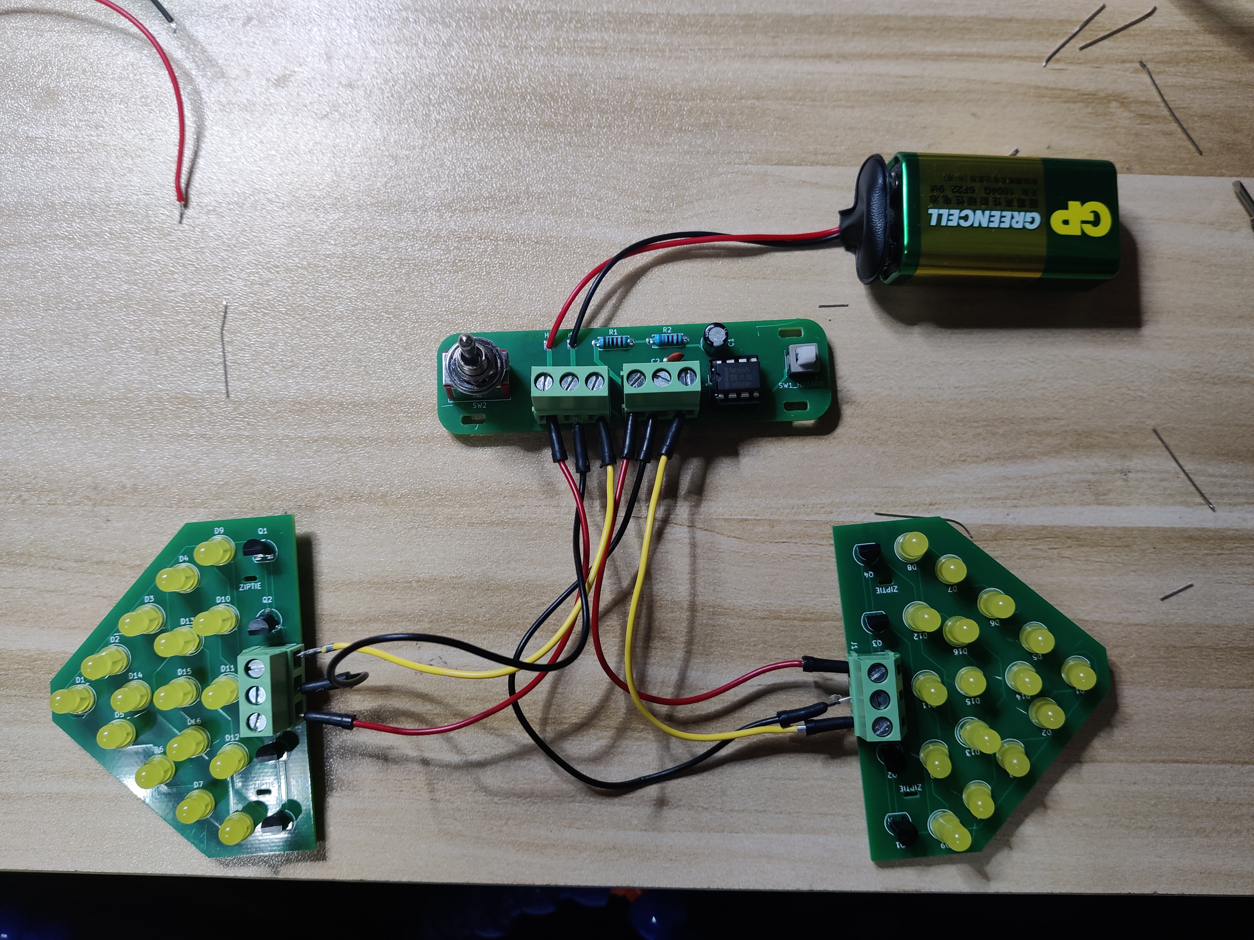
It was oddly satisfying to slide them slowly between my fingers. As I had only a few hours to spare that evening, I finished two LED panels and one controller in quite a haste.
As I was soldering the SP3T switch (leftmost component on controller board, identical one lying in the top right corner of this photo) I realized I made the pads, and consequently holes, too small for the pins to come through. This was because I took the datasheet figures as gospel and failed to leave any space around it. Despite that, I was able to mount it on top just fine, and apply more tin to compensate (sadly, it does not count as SMD).
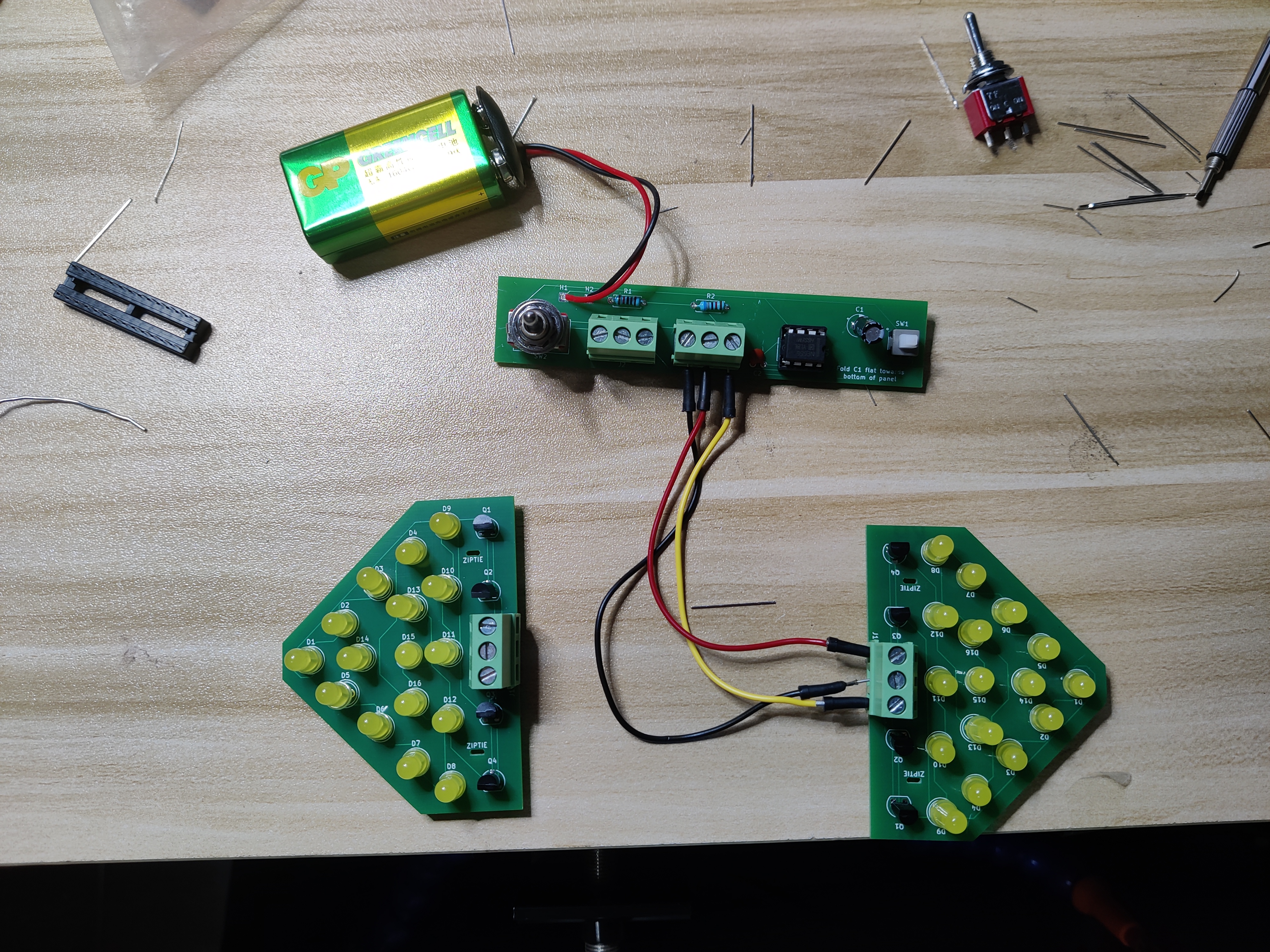
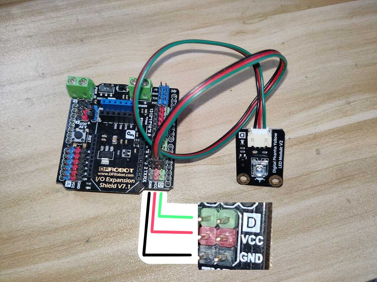
Let's give them a test. First we connect the LED panel to the righthand screw terminal via three jumper wires. (Why three? Because I was a noob and expected everything to work like those modules from Arduino kits: one wire for VCC, one for GND, the other for digital signal. This required external circuit on the LED board, hence the four BJTs.)
Plug in the power. Flip the switch to the right. Yup, it blinks. That's hip.
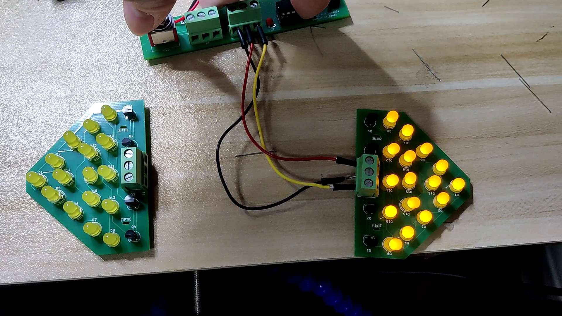
Now connect the wires to the lefthand screw terminal. Flip the switch to the left. And...
It did not blink. The LEDs did not turn on at all. Having excluded faulty soldering, the only possibility was a design error. I examined the schematics and PCB layout, only to find this terrible yet subtle mistake.
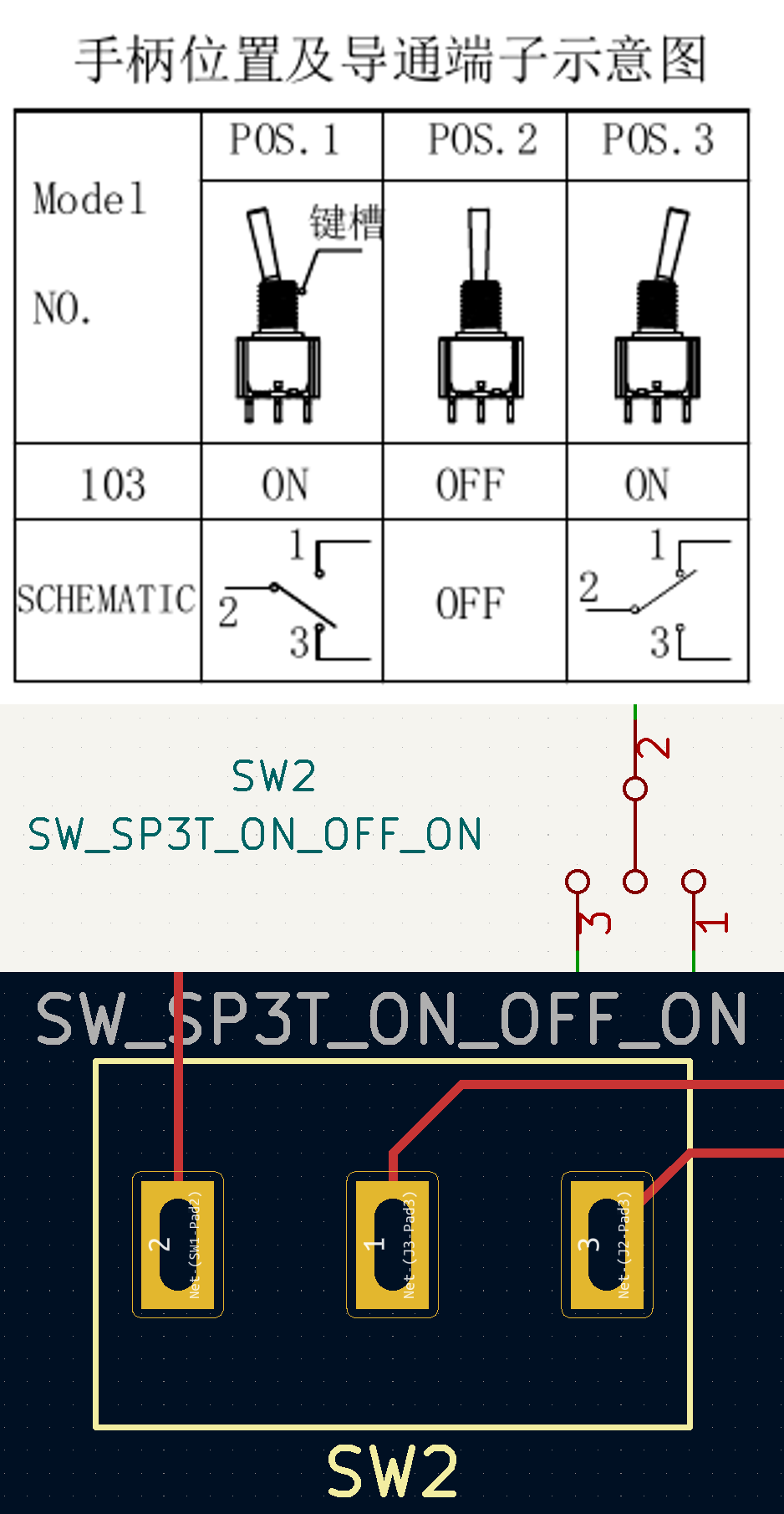
As you can see here the schematics agree with the wiring diagram provided on datasheet in that pins 1, 2, 3 are placed in that order, whereas on the PCB, pin 1 was the middle pin. As a result when I throw the switch to the right, pins 1 and 2 connect, while in the other direction pins 1 and 3 touch, which does nothing actually. Bruh moment.
🎓 Lesson learned: double-check custom footprints
Undersized holes. Faulty pinout. Insufficient track width. All three bugged me so much I decided I would revise it.
Second try
In this attempt I was much more careful, checking everything twice. There was not much to add though, so in the end I barely changed anything else. Among the things I did do there were:
- rounding the corners
- shrinking it horizontally a bit
- cutting out four rectangular holes
The PCB layout:
They arrived in their physical form a few days later, and it was an unnecessary kindness that they made six pieces instead of five. I soldered one of them, and it worked as expected. Yay!
MPEG-4 Video (4.7 MiB)
Installation
It certainly isn't easy to install my creation. My bike hasn't got a slot on the back labeled "blinkers go here". My solution was zipties. I did not mention, but in my second LED panel design I added two holes for ziptie insertion (a bit too small again, but works fine). In addition, I needed something waterproof and transparent to enclose it in. This gave rise to the Greatest Hack of All Time. Guess what is waterproof and transparent?
Bottles.
Plastic bottles are waterproof by definition and transparent if you peel off the thin film glued to it. So I headed to the store and bought a reasonably large bottle of tea. The cross section of said bottle was not round, but rather a square, which turned out handy because the PCBs fit in diagonally and were thus locked in place. To actually put them in I had to cut off its neck with a knife; the opening I later sealed up with tape. Holes were drilled in the back of the bottle for the ridiculous six copper wires and two zipties, and the seams were covered with tape as well.
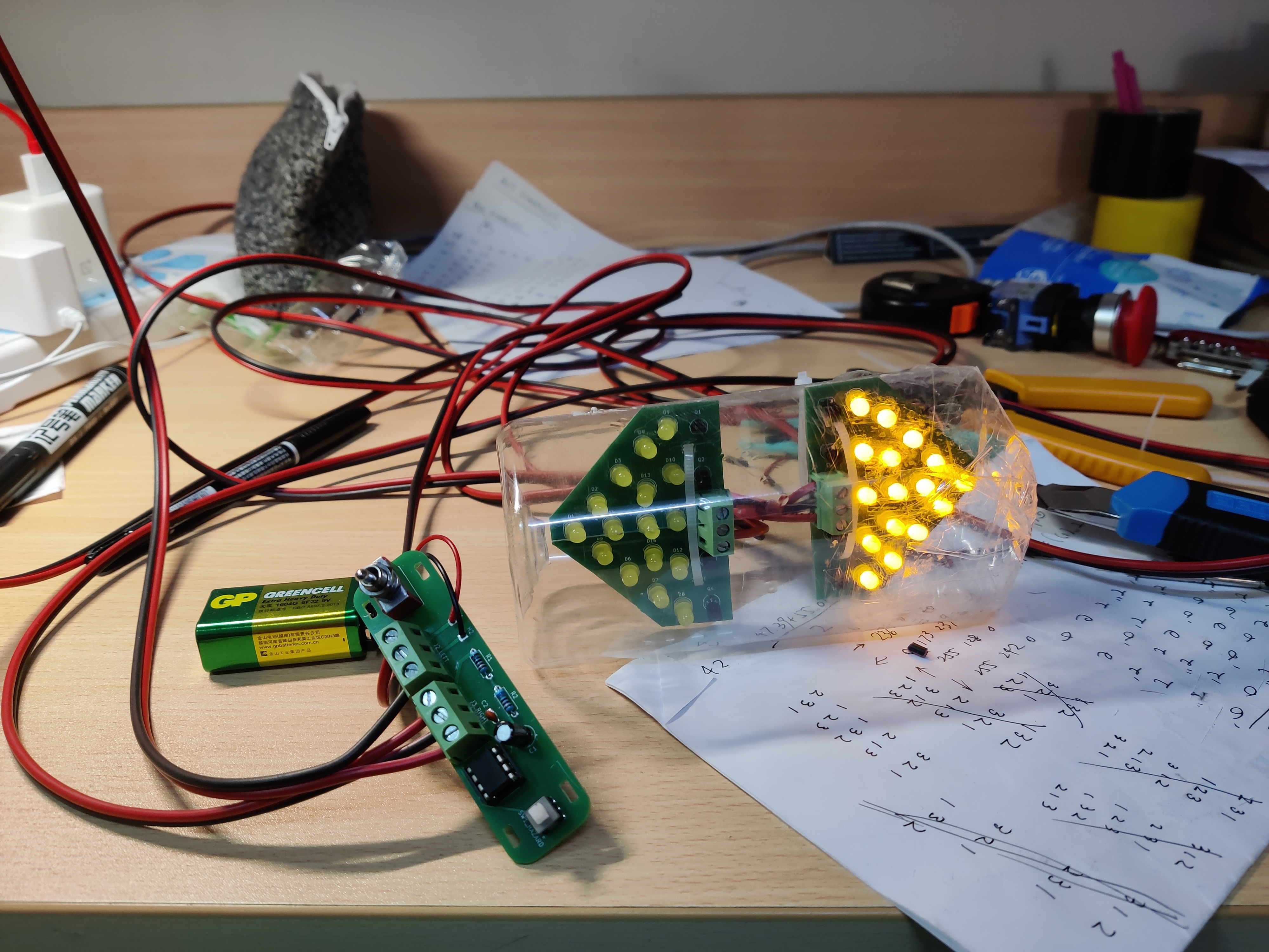
🎖️ Achievement made: Hackus Ultimus
The wires were some red/black pairs. I'm not sure what gauge they are, but they sure are thicc. To install all these I got up early the next day, literally just taped the battery and the controller on the handlebar, ran the entire length of wires to the back, where the bottle was ziptied to the steel rack and reinforced with duct tape. Here is a demo, which is super short and taken at night so you can't see anything but you get the idea:
I went around like this for a week or so because I was waiting for something to complete — and that was the 3D printed case for the controller.
Going 3D
I had always wanted to make a 3D-printed thingie for whatever purpose. This time it was really evident that I should do it. So I went ahead and grabbed FreeCAD to see if my hollow knowledge of 3D modeling inherited from Autodesk Inventor®™© could work out. I kept getting stuck, regurgitating many of the steps that got messed up somehow, but finally reached a pretty nice result.
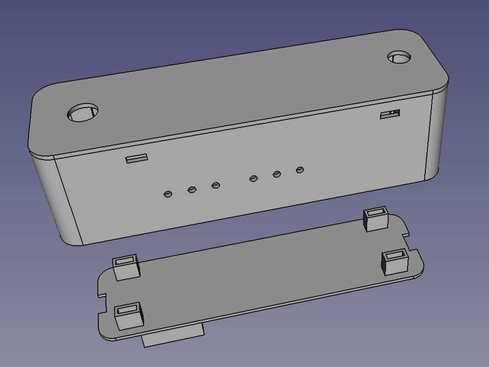
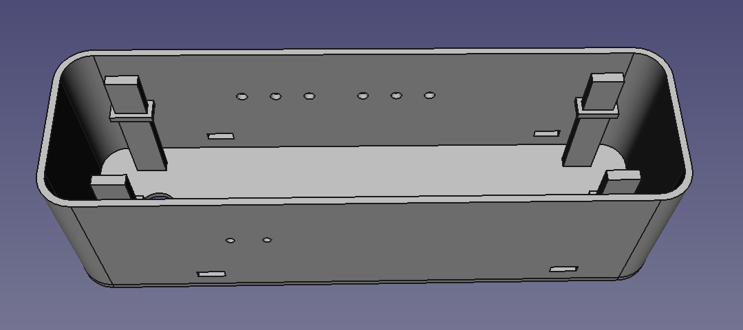
🎖️ Achievement made: First independently made 3D model
As you can see here, I made four pillars along four corners, intended to go through those four holes I made on the PCB, then fit into the slots on the bottom (reverse lid?). I would then mount it all onto the handlebar with two zipties and, of course, tape.
It would work well, right?
No.
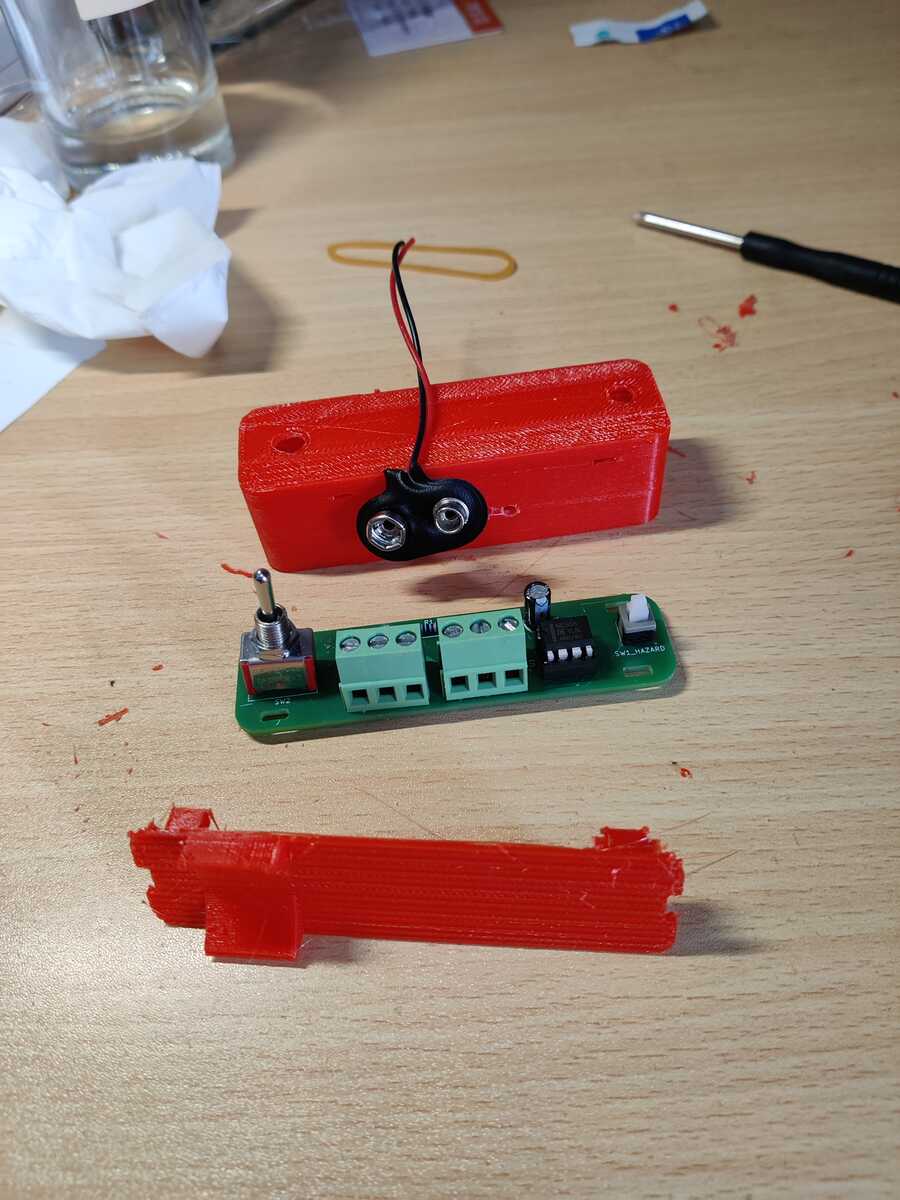
I kinda overestimated FDM technology, and although my switches align with the holes, apparently there are flaws.
- It looked flimsy after the support was removed
- The wire holes... they're just tiny and it was a massive pain to thread the wires inside given the amount of residue. It even cracked a bit.
- The pillars barely made it through the PCB holes; the slots broke within seconds.
The lesson I learned here is 3D printing isn't magic. It's not gonna faithfully reproduce every feature if they're too fine, and the strength will likely be meh. Anyway,
🎖️ Achievement made: First 3D printed object
I decided to just let it be and pushed the controller board inside.

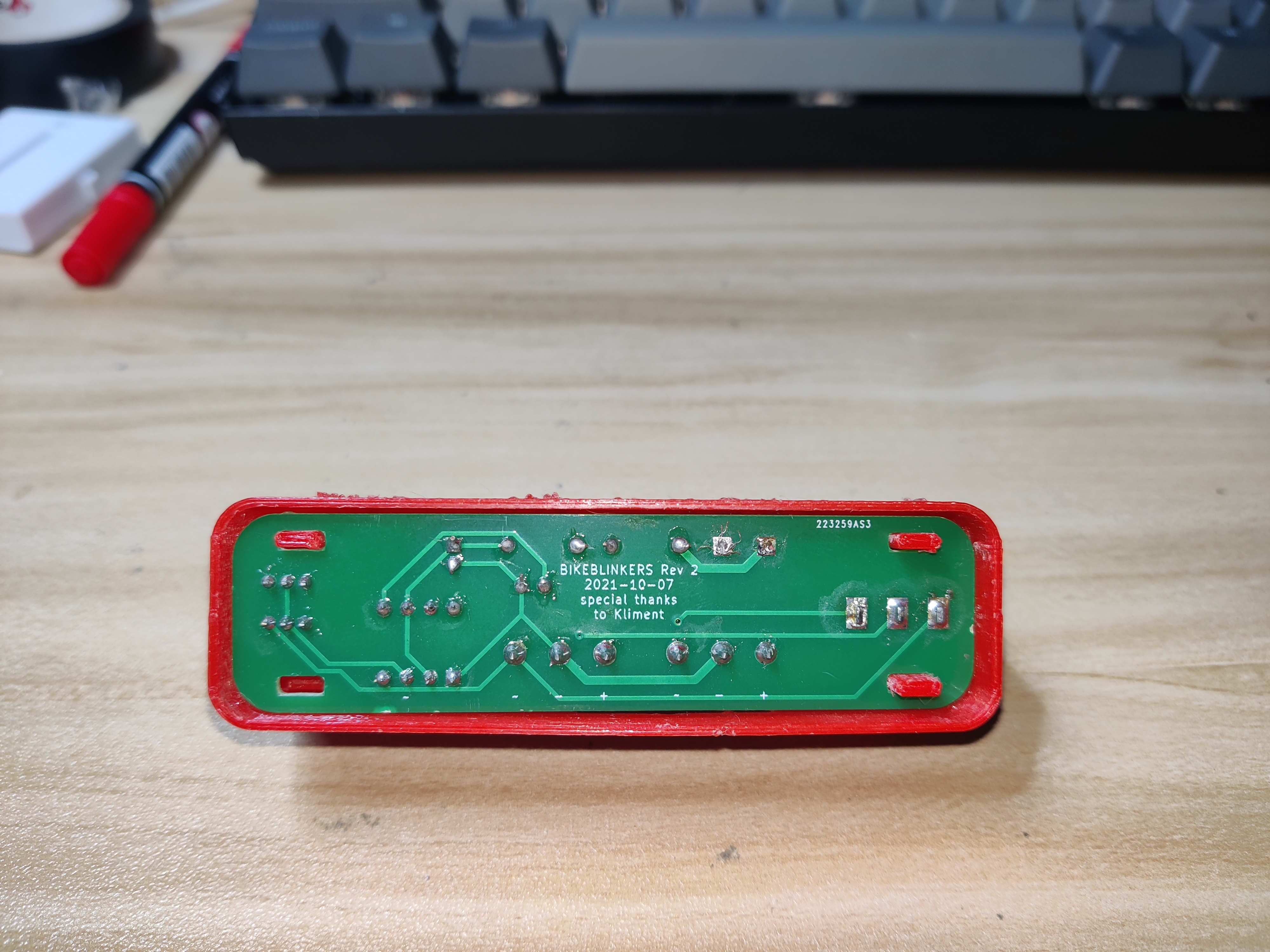
At this point, Bikeblinkers seems complete. Big cheers moment!
Despite the blinkers I continued lifting my arm as a secondary indicator because
- They are too dim to be seen in sunlight. Blame the common collector configuration. (See workaround below)
- I would not expect reckless drivers/cyclists to notice my tiny blinkers, my arm, or me
- I cannot be 100% sure the blinker is properly working
Common collector configuration: the workaround
As said above, this kind of configuration is really unwise. You can't get much power gain. So, as a workaround, if I want to turn on the LEDs on the panel, I could send 9V directly to the base. Base and emitter act like a PN junction and just let everything through, reaching a higher current. However a 555 can't really output that much current, so we'll have to take other measures, such as more transistors, this time in common emitter configuration.
Conclusion
The project was successful overall. Am I satisfied? Yes and no.
- ✔️ I learned to make PCBs (albeit terribly and error-prone)
- ✔️ The "Bikeblinkers" worked as advertised
- ❌ 555's output and toggling of the switch are not synchronized and lead to delayed or incomplete blinks

- ❌ It is just a pair of blinkers and does nothing more
Oh no, Fred. You are not letting that dreaded Feature Creep kick in.
HEll YEs i Totally Am
Next episode: Byseekel