blobcat PCB
2023-07-06
▲ There are ten more LEDs on the back.
Fun? Yes. Stupid? 100%. This is my second attempt at purely artistic PCBs (the first failed).
TechJI is the organization I work in since 2021. I will retire from director this month, so I'm designing this as a farewell gift.
Repo: blobcat-pcb on Codeberg
Oh, yes, and this makes a great SMT soldering exercise for beginners because all the parts are nowhere near out of stock (I don't know who'll die first — me or NE555).
Artistic design

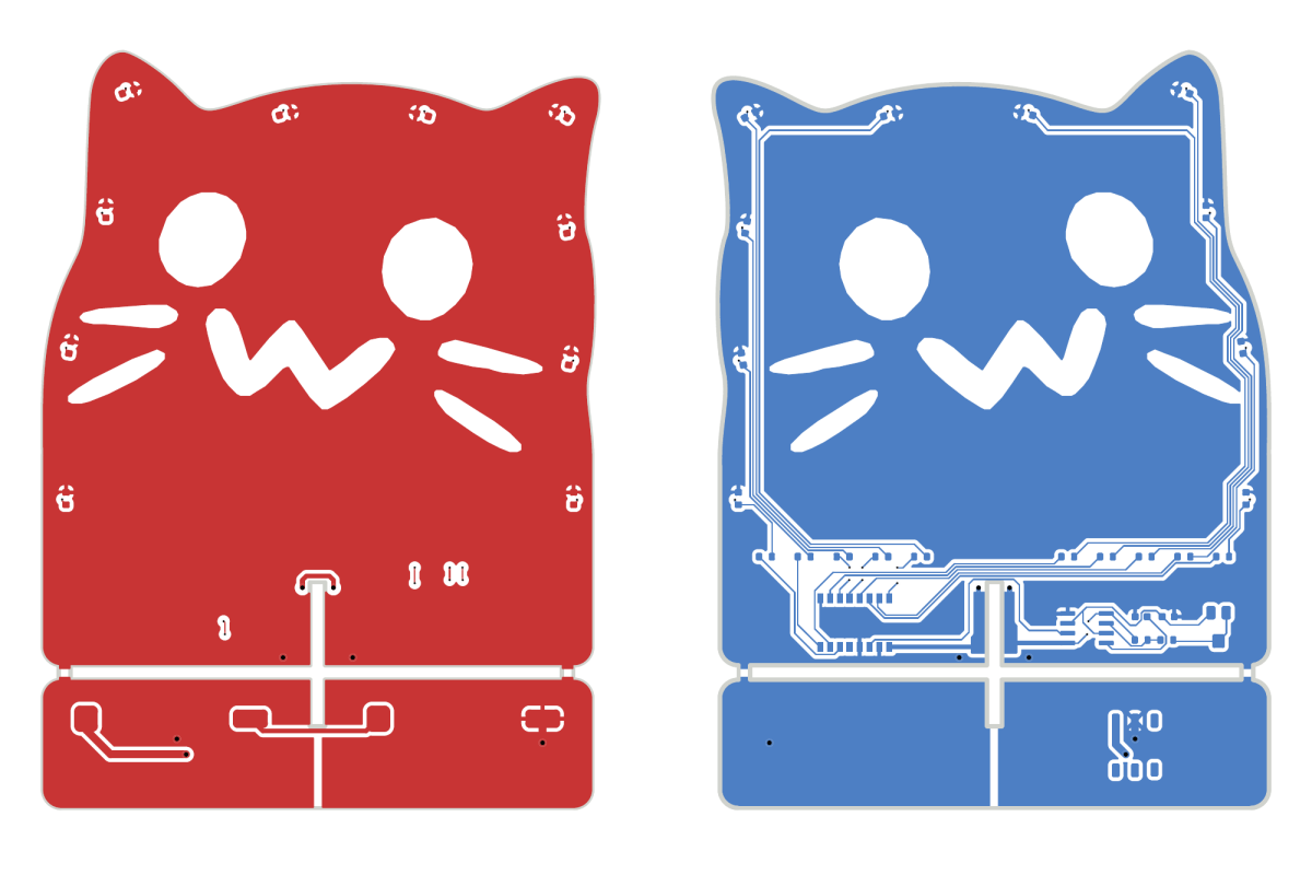
Board outline is based on this svg of :blobcat_paw:.
I would have printed the pattern in black, if black silkscreen wasn't 10x more expensive.
Structural design
You can snap the board in two and solder them up. The solder joints provide structural support and electrical conduction from batteries to circuitry. I took the idea from a project I saw earlier, but forgot which.
Logic design
I referenced copied FrostAutumn's design on LCSC
OSHWHub.
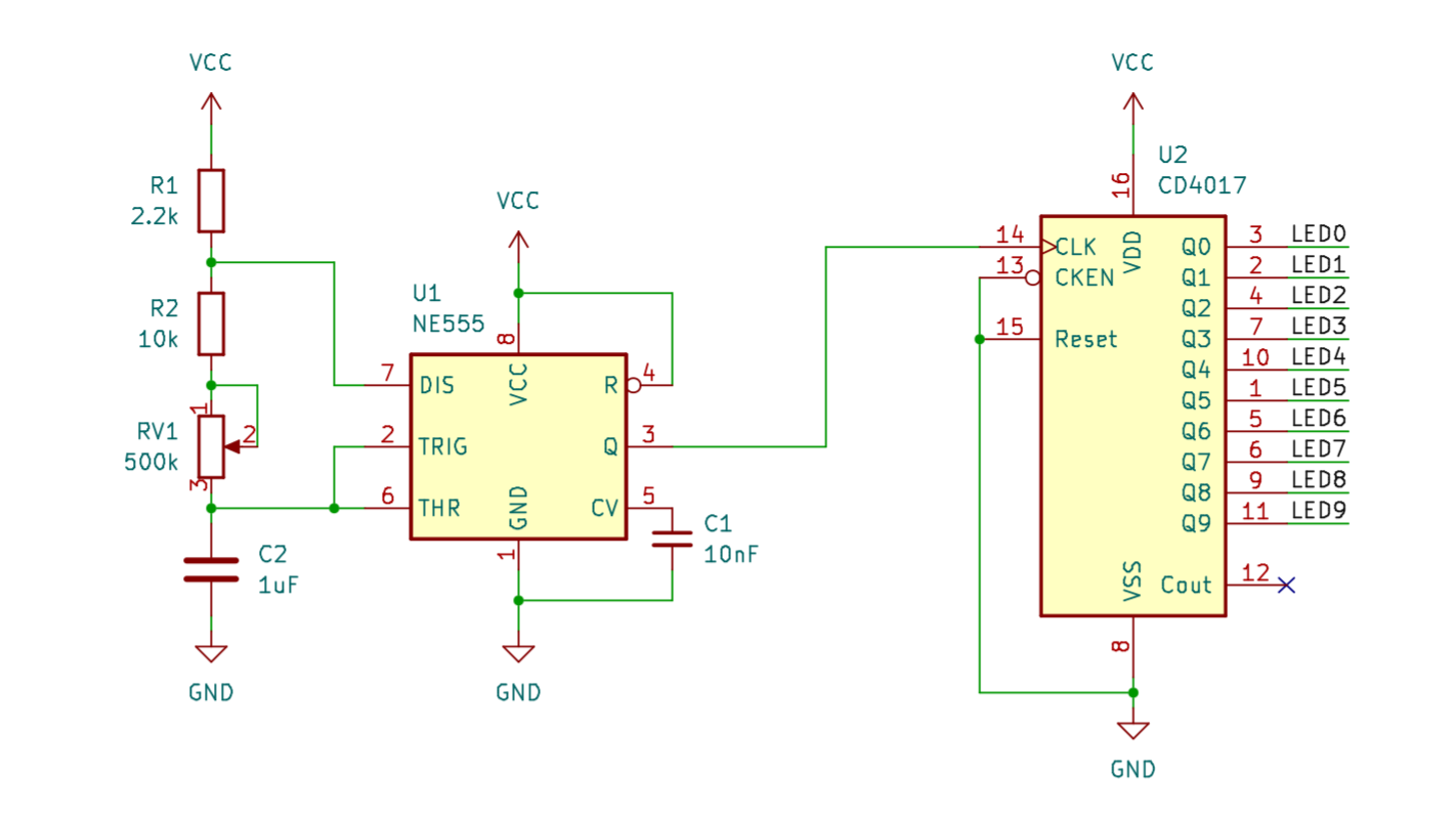
- NE555 in astable mode provides clock signal for CD4017
- CD4017 outputs high level to exactly one LED
- Each rising edge, a different LED turns on
- Effect: marquee
- Speed adjustable with RV1
Power design
At first I wanted to use only one CR2032, just like FrostAutumn's design. Datasheet says NE555 needs 4.5V, so I'll need a boost converter. With the converter comes a lot of annoying stuff, like inductors, so I just said "fuck it" and threw away the converter idea.
Now the board is powered by two CR2032s.
DIY Manual
If you want to build your own, expand this
BOM
All R, C, and D are 0603.
- U1: NE555 SOIC-8
- U2: CD4017 SOP-16
- R1: 2.2k (anything between 1k to 5k should work)
- R2: 10k (or somewhere near that)
- RV1: 500k
- C1: 10nF
- C2: 1uF
- R10-19: 120 (120 to 180 is safe)
- D10-19: LEDs, arbitrary colors, note that each reference is two LEDs
- SW1: SPDT, 6 pins
- BT1,2: No idea what the package is, I just happen to have some
Fabrication
The fab may charge extra because they might mistake the battery board for a separate design. I negotiated out of paying for it.
Assembly
When soldering, use flux generously.
- Snap board into main board and battery board
- File down the four snapped bits
- Solder main board (the side with more parts first)
- Solder battery board (make sure BT1,2 don't jiggle)
- Rotate battery board by 90 degress
- Insert into main board
- solder 4 pairs of copper strips at crossing
- Insert CR2032 batteries
- Turn on SW1
Note on LEDs
LEDs typically have a green marking on the front side. It is the cathode. On the PCB, a U shape surrounds the LED. The valley is the cathode. It appears more yellow because it is connected to the ground plane.
You should use the same color for each pair, because they share the same voltage. If you solder red and blue, only red will light up, because it requires less voltage.
Troubleshooting
- It doesn't work at all
Probe voltage across VCC and GND. If too low, check soldering on BT1,2 and SW1. Make sure BT1,2 lay completely flat and don't jiggle.
If still no, check soldering on U1,2, C1,2, R1,2 and RV1. Gently nudge pins with tweezers. Does it jiggle? If so, rework.
- An LED doesn't work
First, check polarity.
If the LED on the other side works, check if they're the same color. If you're not sure, replace.
If neither LED works, check the resistor (R10-R19) and U2.
Bugs
Battery
CR2032 batteries exceed lowest board outline, assembly tips slightly.
When using v0.4.2, solder BT1,2 (battery holders) a few millimeters above footprint.
Fixed in v0.4.3.
Filled zones
Thermal reliefs work too well. When soldering BT1,2 and copper strips, you need to be patient. Heat will dissipate into filled zones. Do not touch the board surface; it will scald you. Use a clamp if possible.
Important!
Do not put blobcat v0.4.2 on a conductive surface. It will short BT1.
Dangers of overcomplicating
In earlier iterations, I massively overcomplicated the project by:
- routing 20 pairs of LEDs instead of 10
- driving LEDs with BJTs for fear of frying CD4017
I managed to route them, but it was a pain. What's worse, I discarded the design, which technically marks my efforts moot. All this work for nothing.
I don't know what the complexity of routing N parts is, but it definitely is higher than O(N).
Don't overcomplicate your projects, kids!
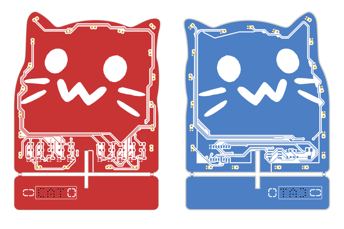
Copper layers in ▲ v0.2; ▼ v0.4